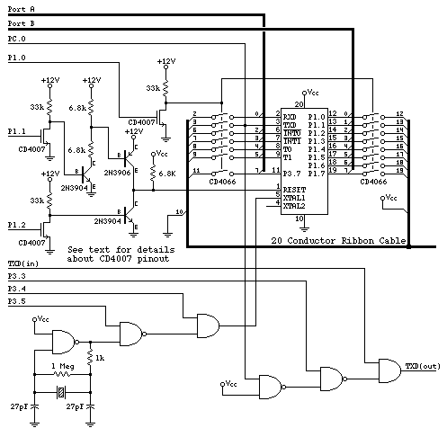
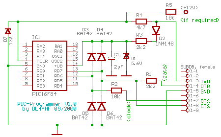
Serial Flash Memory Programmer Schematic
FlashProg is USB base flash memory programmer to work with 3.3V serial flash memory devices. This programmer is specifically design to read, program and configure 25x series, serial flash memory devices which are commonly used to store BIOS in PC mainboards. FlashProg programmer is built around Atmel ATmega8A microcontroller with standard through-hole type components and it support for both 32 bit and 64 bit Windows and Linux operating systems. All the compiled binaries for both the platforms are available at project home page.
Or as a stand-alone serial flash programmer for the Atmel. Circuit diagram of the SPI Flash programmer. The Flash & Eeprom memory. In-Circuit Serial Programming. For PICmicro FLASH devices, the entire code memory can be rewritten with new code. In PICmicro OTP devices, new code segments and parameter tables can be easily added in program memory areas left blank for update purpose. Often, only a portion of.
This programmer use very few components and it can be easily constructed on breadboard or on PCB. Both EAGLE and PDF versions of PCB design files are available with the project package. This project is an open source hardware project and all it’s source codes, design files and documentation are available.
Introduction Programming Dual SPI memory devices is a common use case for the Promira™ Serial Platform with SPI Active Level 1 and 2 Applications. There are several ways to do this with the Promira™ Serial Platform, including using Control Center Serial, Flash Center, or the Promira API. This article focuses on how to take the information in a flash datasheet and execute the commands in Control Center Serial. Although the following describes the Micron SPI Flash N25Q00AA 3.3V SOIC 16 assembled on the, similar steps can be used for other devices. The goal of this article is to demonstrate how to write several bytes to a specific address and then read back those bytes. Overview In this article the Promira platform erases the N25Q00AA, and writes and reads three bytes (0x0A 0x0B 0x0C) from address 0x000008.
Here the Promira platform is the SPI master and the N25Q00AA on the Flash SOIC-16 Socket Board - 10/34 is the SPI slave. The Promira platform is connected to the N25Q00AA on the Flash SOIC-16 Socket Board - 10/34 through the 34-34 I2C/SPI cable. The Promira platform supplies 3.3V SPI signals and 5V VDD signal to the Flash SOIC-16 Socket Board - 10/34. For additional information take a look at the and the N25Q00AA Details For reference, listed below are several of the N25Q00AA commands that are used in this article. Figure 1 shows partial of the N25Q00AA commands List. See the N25Q00AA datasheet for additional details. Figure 1: N25Q00AA Commands List Write Enable Command The N25Q00AA write enable command (0x06) sets the write enable latch bit.
The write enable latch bit must be set prior to any write command (Program, Erase, Write, Enter 4 Byte Address Mode, and Exit 4 Byte Address Mode). Figure 2: N25Q00AA Write Enable Command Dual Input Fast Program Command The N25QQ00A dual input fast program command (0xA2) is used for programming dual SPI data. Figure 3: Dual Input Fast Program Command Dual Input/Output Fast Read Command The N25QQ00A dual input/output fast read command (0x3B) is used for reading dual SPI data. Figure 4: Dual Input/Output Fast Read Command Writing and Reading Guidelines.
Connect the Promira platform USB connector to the PC USB connector. Follow the instructions in of the Promira platform user manual to configure the Ethernet over USB interface. and unzip the latest version of Control Center Serial. Connect the Promira platform I2C/SPI connector to the Flash SOIC-16 Socket Board - 10/34 with the N25Q00AA through 34-34 cable.
Launch Control Center Serial. Connect Control Center Serial to the Promira platform. Click Adapter, and choose Connect. Select the Promira platform. Click OK to connect to the Promira platform. Click Adapter, and choose Multi I/O SPI.
Click Adapter, disable I2C Pulls-Ups, enable Target Power (Pin 4,6), disable IO Power (Pin 22,24), and configure Level Shift to 3.3V. Configure Promira SPI Mode to 0, Bit Order to MSB, and SS Polarity to Low, and Bitrate to 40000 KHz. Configure Promira to dual SPI mode. Configure IO Mode to: Single, Single, Single. Read the enchanced volatile configuration register. Enter 65 00 in Command. Leave Addr & Data empty.

Click Send. Verify 00 DF is read back. Send the write enable command to set the Write Enable Latch bit. Enter 06 in Command. Leave Addr & Data empty. Click Send. Change the IO mode to dual by modifying the enhanced volatile configuration register.
Enter 61 9F in Command. Leave Addr & Data empty. Click Send. Configure IO Mode to: Dual, Dual, Dual. Read the enchanced volatile configuration register.
Arduino Serial Flash Memory

Serial Flash Memory
Enter 65 in Command. Leave Addr & Data empty. Enter 1 in Number of Words to Read. Click Read. Verify 9F is read back.

Read the memory device ID. Enter AF in Command. Leave Addr & Data empty.
Enter 3 in Number of Words to Read. Click Read. Verify 20 BA 21 is read back Figure 5: Configure Promira to Dual SPI Mode. Write and Read Memory.